Create IPsec tunnels in Cisco SD-WAN
Before you begin:
These are the high-level steps that are required to create a primary and secondary tunnel between Cisco SD-WAN and SIA.
To create IPsec tunnels in Cisco SD-WAN:
-
(Optional) Configure service routing.
If your organization uses ETP Client, make sure you disable the client in policies that are associated with the IPsec tunnel locations.
Create a Secure Internet Gateway (SIG) feature template
Complete this procedure to create a SIG template that you apply to your SD-WAN device.
To create a SIG feature template:
-
Log into Cisco vManage.
-
In the navigation menu, select Configuration > Templates.
-
Click Feature, and then click Add Template.
-
Select your routing device and for the template, go to the VPN section and click Cisco Secure Internet Gateway (SIG).
-
Enter a name and description for the template.
-
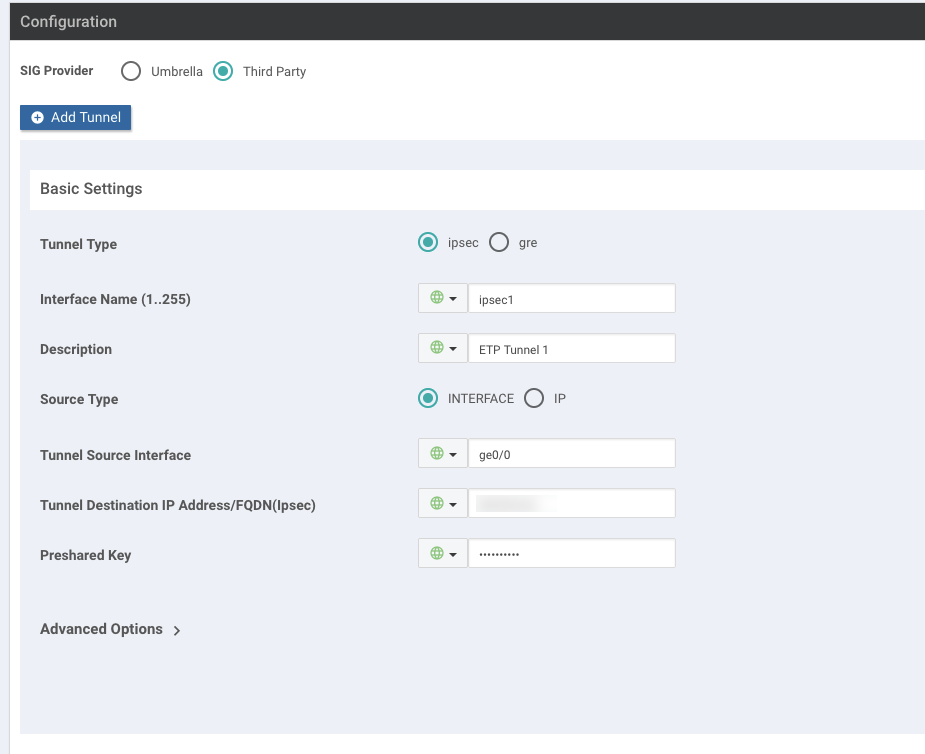
In the Configuration section, select Third Party as the SIG Provider.
-
Click Add Tunnel.
-
Under Basic Settings, complete these steps:
-
For the Tunnel Type, select ipsec.
-
In the Interface Name field, enter
ipsec1or include a different number. -
For the Source Type, select INTERFACE or IP.
-
Depending on the source type you select, in the Tunnel Source Interface field, enter the name of the source interface or the IP address for the tunnel. This interface usually faces the Internet.
-
In the Tunnel Destination IP address/FQDN(Ipsec) field, enter the primary IPsec FQDN:
primary.ipsec.akaetp.net -
In the Preshared Key field, enter the PSK key that you generated and entered in SIA.

-
-
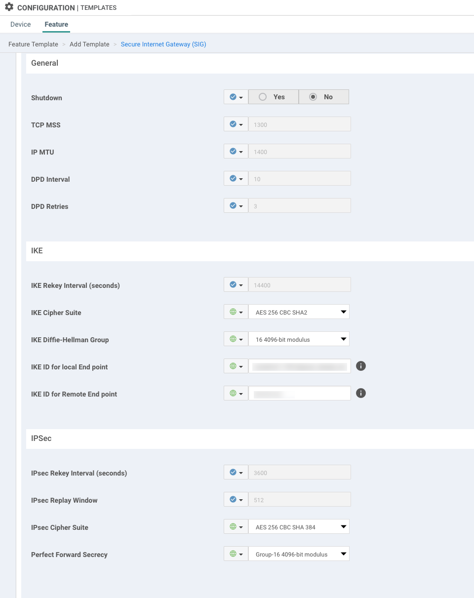
Click Advanced Options.
-
In the IKE section, do the following:
-
In the IKE Cipher Suite menu, select the desired setting.
-
In the IKE ID for Local End Point field, enter the IKE identifier that you defined in SIA.
-
In the IKE ID for Remote End Point field, enter
primary.ipsec.akaetp.net

-
-
In the IPSec section, select the desired security settings.
-
Click Add.
-
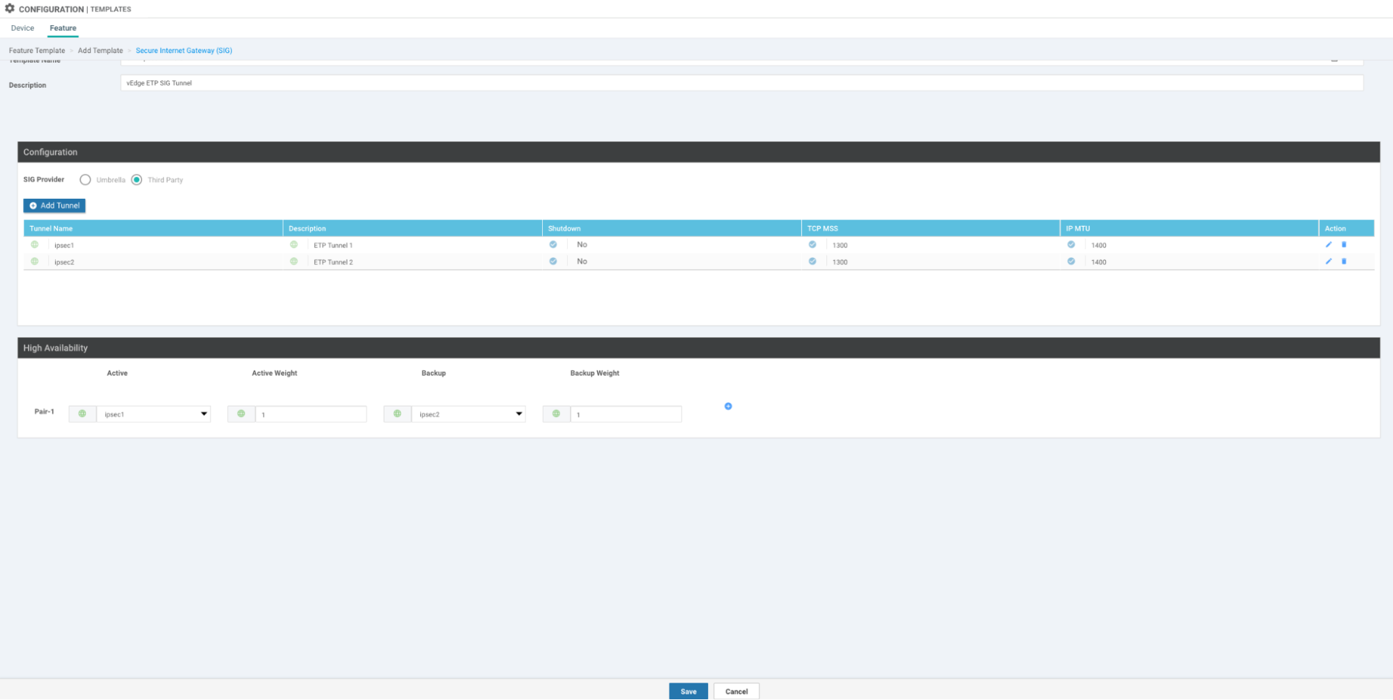
Repeat steps 7-12 for the second tunnel. Make sure you enter the IPsec FQDN (
secondary.ipsec.akaetp.net) that’s associated with the secondary tunnel. -
Configure high availability settings:
-
If you would like the first tunnel to be the active tunnel and the second to be the backup, under Active, select the first tunnel and in the backup menu, select the second tunnel.
-
Save the template.

-
-
In your device template, select the template you created as the Cisco Security Internet Gateway setting for VPN 0:
-
In the Device tab, click your device template.
-
Navigate to the Transport & Management VPN section.
-
Under Cisco VPN 0, select the template you created for the Secure Internet Gateway setting.
-
Update the device template.
-
In the left pane, select the device and click Config Diff to preview the differences between this update and the configuration that’s currently used.
-
Click Configure Devices to push the configuration to your devices.
-
Next steps:
-
Monitor the device:
-
In the main menu, select Monitor > Network.
-
Select the device that you need to monitor.
-
Click Real Time.
-
In the Device Options field, enter
IPsec IKE Sessionsto view information on the sessions. -
In the Device Options field, enter
Interface Statisticsand in the filter, enteripsecto view details on the tunnels.
-
Create and activate a centralized policy
Before you begin:
Create a Secure Internet Gateway (SIG) feature template
Complete this procedure to create and activate a centralized policy. A centralized policy defines the flow of traffic and routing decisions in the overlay network. For more information, see the Cisco SD-WAN documentation.
If you prefer to configure a default service route instead, see (Optional) Configure service routing.
To create and activate a centralized policy:
-
In the Cisco vManage navigation menu, select Configuration > Policies.
-
From the Centralized Policy tab, click Add Policy.
-
Create groups of interest based on the lists you want to create. For example, you can create site lists, applications lists, and more. For more information, see the CIsco SD-WAN documentation.
-
Configure traffic rules:
-
Click Add Policy. Select Create New.
-
Enter a name and description for the policy.
-
Click Sequence Type in the right pane and in the dialog that appears, select Custom.
-
Click the plus sign icon to add a sequence rule.
-
Under Match, if you created an application list, click Applications/Application Family List. In the drop-down list, select the list.
If you did not create an application list, make sure you click the Destination Port tab and enter 80 and 443 as the destination ports.
-
Click the Action tab and in the Sequence rule, select the Accept radio button.
-
Select Secure Internet Gateway.
-
Click Save Match and Actions.
-
In the right panel, click Default Action and select Accept as the action. Click Save Match and Actions.
-
-
Click Save Data Policy.
-
Apply policies to sites and VPNs:
-
In the Traffic Data tab, click New Site List and VPN List.
-
Add the site lists and VPN lists that you previously created.

- Click Add.
-
-
Click Preview to view the configured policy in CLI format.
-
Click Save Policy.
-
Activate the policy:
-
From the Centralized Policy tab, go to the policy you created and in the menu, select Activate.
-
In the dialog that appears, click Activate.
-
(Optional) Configure service routing
You can configure a default route through a service route instead of creating a centralized policy.
Unless you configure firewall rules that allow non-HTTP traffic, non-HTTP traffic is dropped.
To configure service routing:
-
In the navigation menu, select Configuration > Templates.
-
From the Feature tab, click the menu option for the Service VPN template where you want to configure service routing and select Edit.
-
Navigate to the Service Route section and click New Service Route.
-
Enter this as the prefix:
0.0.0.0/0 -
Enter SIG as the service.
-
Click Add.
-
Update the template:
-
For the device, click the menu icon and click Edit Device Template.
-
Click Update and then click Next.
-
Click Configure Devices to push the configuration settings.
-
Updated about 2 years ago
